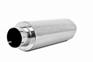
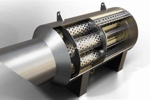
The component designed to prevent the emission of flammable debris from an internal combustion engine’s exhaust system and to reduce exhaust noise is generally positioned at the end of the exhaust system. This placement ensures that all exhaust gases pass through the device before being released into the atmosphere. Its location is critical for effective suppression of sparks and the attenuation of sound waves produced by the engine.
The importance of containing sparks emitted from engines operating in areas with dry vegetation cannot be overstated, as it mitigates the risk of wildfires. Simultaneously, muffling exhaust noise contributes to noise pollution reduction. Historically, these devices have been essential in industries such as forestry, construction, and off-road vehicle operation, where the potential for igniting flammable materials is elevated. This functionality provides a safer operating environment and promotes regulatory compliance.
The precise configuration and attachment method of this crucial part can vary depending on the specific engine type, vehicle design, and applicable regulatory requirements. Further details regarding specific placements, maintenance procedures, and regulatory guidelines are discussed in subsequent sections.
Locating Spark Arrestor/Muffler Components
Effective location and maintenance of the component responsible for spark suppression and exhaust noise reduction are essential for safety and compliance. The following tips provide guidance on this crucial aspect.
Tip 1: Consult the Vehicle or Equipment Manual: The manufacturer’s documentation offers the most accurate information regarding the specific positioning of the spark arrestor/muffler assembly on a given model. Diagrams and instructions can significantly aid in its identification.
Tip 2: Inspect the Exhaust System’s Termination Point: The device is typically situated at the furthest point along the exhaust system, immediately prior to the point where exhaust gases are released into the environment. A visual inspection of this area will often reveal its presence.
Tip 3: Identify Maintenance Access Points: Some models incorporate removable screens or baffles requiring periodic cleaning or replacement. Look for accessible points, often secured with fasteners, that permit access to these internal components. These features are usually at the device’s furthest termination point.
Tip 4: Examine for Markings or Labels: Many spark arrestor/muffler assemblies feature stamped markings or labels indicating compliance with relevant regulatory standards. These markings can aid in verifying that the correct component is installed and maintained.
Tip 5: Listen for Changes in Exhaust Tone: A malfunctioning or damaged spark arrestor/muffler can often result in a noticeable increase in exhaust noise. This auditory cue can indicate a problem requiring immediate attention and component inspection.
Tip 6: Check for Soot or Carbon Buildup: Excessive soot or carbon deposits accumulating around the devices exhaust port can indicate restricted airflow or a need for cleaning. Such deposits can impair performance and increase fire risk.
Effective location and regular maintenance of the spark arrestor/muffler are critical for ensuring proper functionality, minimizing environmental impact, and complying with safety regulations.
Understanding these location principles and regularly applying these tips will improve the effectiveness of the device and ensure adherence to relevant standards.
1. Exhaust System End
The positioning of a spark arrestor/muffler at the exhaust system end is a deliberate design choice predicated on fundamental principles of combustion engine safety and environmental responsibility. This location represents the last point of intervention before exhaust gases are discharged into the environment, providing a critical opportunity to mitigate the risk of fire ignition caused by errant sparks. The exhaust system end, by definition, is the terminal point of the exhaust stream, ensuring that all combustion byproducts, including incandescent particles, must pass through the spark arrestor. For instance, in off-road vehicles operating in forested areas, locating the spark arrestor here is essential to prevent wildfires. The effect of this placement is a significant reduction in the likelihood of igniting dry vegetation or flammable materials in the vicinity of the vehicle’s operation.
The importance of locating the spark arrestor at the exhaust system’s terminal point is further underscored by regulatory requirements in many jurisdictions. These regulations often mandate that all internal combustion engines operating in designated high-risk areas, such as national parks or forests, must be equipped with a functional spark arrestor positioned at the exhaust system end. Failure to comply with these regulations can result in substantial fines and operational restrictions. Real-world examples abound, where neglecting this component has led to devastating wildfires, highlighting the practical significance of adhering to proper installation and maintenance guidelines. The U.S. Forest Service, for example, actively enforces spark arrestor requirements on equipment used within national forests to prevent fire hazards.
In summary, placing the spark arrestor/muffler at the exhaust system end is a critical measure for fire prevention and environmental protection. This location ensures that all exhaust gases are filtered for incandescent particles, effectively mitigating the risk of ignition. Challenges associated with this placement may include increased maintenance requirements due to carbon buildup, but the benefits in terms of safety and regulatory compliance far outweigh the drawbacks. This understanding is directly linked to the broader theme of responsible engine operation and minimizing the environmental impact of internal combustion technologies.
2. Engine Exhaust Outlet
The engine exhaust outlet serves as the immediate point of expulsion for combustion byproducts, establishing a critical juncture in determining spark arrestor/muffler placement. The proximity of the device to this outlet directly influences its efficiency and operational effectiveness in containing sparks and mitigating noise.
- Immediate Spark Quenching
Positioning the spark arrestor near the engine exhaust outlet facilitates immediate quenching of incandescent particles before they can travel farther and potentially ignite flammable materials. This proximity reduces the opportunity for sparks to retain heat and momentum, enhancing overall fire prevention capabilities. Chainsaws provide a prime example, where the spark arrestor is often integrated directly into the muffler attached to the exhaust outlet, preventing sparks from igniting sawdust.
- Compact Design Integration
Close proximity to the engine exhaust outlet allows for more compact and integrated designs. Manufacturers can incorporate spark arresting elements directly into the muffler assembly, streamlining the exhaust system and minimizing overall size and weight. This integration is particularly beneficial in small engine applications such as handheld power equipment, where space constraints are significant.
- Thermal Management Considerations
The high temperatures present at the engine exhaust outlet necessitate careful consideration of thermal management when positioning the spark arrestor/muffler. Heat shields and appropriate materials selection are critical to prevent component failure and ensure safe operation. Insufficient thermal protection can lead to premature degradation of the spark arrestor, compromising its effectiveness and potentially creating a fire hazard.
- Accessibility for Maintenance
While close proximity offers advantages in terms of performance and design, it also affects accessibility for maintenance. The spark arrestor must be readily accessible for cleaning and inspection to ensure continued functionality. Design compromises may be necessary to balance performance with ease of maintenance, such as incorporating removable access panels or modular components.
The facets of immediate quenching, design integration, thermal considerations, and maintenance accessibility collectively underscore the importance of the engine exhaust outlet as a key factor in determining the placement of spark arrestor/mufflers. Different engine types and applications necessitate varying approaches to optimize these considerations, but the fundamental goal remains consistent: effectively mitigating fire risk and reducing noise emissions.
3. After Catalytic Converter
Positioning a spark arrestor/muffler after the catalytic converter represents a specific design choice with implications for both emissions control and fire safety. The catalytic converter, responsible for reducing harmful exhaust pollutants, operates at high temperatures. Locating the spark arrestor downstream mitigates the risk of uncombusted fuel or other volatile compounds within the exhaust stream igniting on the hot surfaces of the arrestor itself. This arrangement is particularly relevant in systems where catalytic converters are highly efficient, as they typically generate less particulate matter that a spark arrestor would otherwise need to capture upstream. Therefore, the effect of this location is an integration of two critical functionalities: emissions reduction and spark suppression, without compromising the operational safety of either component. A practical example can be found in certain modern off-road motorcycles equipped with catalytic converters to meet stringent emissions standards. The spark arrestor is typically positioned after the converter to avoid interfering with its function.
However, the placement after the catalytic converter may lead to certain considerations in terms of maintenance and efficiency. While the catalyst reduces pollutants, it doesn’t eliminate all particulate matter. Positioning the spark arrestor downstream means it may still need periodic cleaning to remove accumulated carbon deposits. Furthermore, some designs incorporate a combined catalytic converter/muffler/spark arrestor unit for compactness and efficiency, presenting a more integrated approach to emissions control and spark suppression. These integrated systems require careful design to ensure optimal performance and longevity of all components, and in practice this means that the location of each functional element must be carefully balanced against performance and space constraints. Examples of this can be found on some ATVs and UTVs.
In summary, the “after catalytic converter” location for spark arrestor/mufflers highlights a design approach that seeks to harmonize environmental protection and fire safety. While this location offers advantages in terms of component interaction and reduced fire hazards, it also presents challenges related to maintenance and overall system integration. Understanding these trade-offs is crucial for engineers and technicians involved in the design, installation, and maintenance of exhaust systems in various applications, particularly those subject to stringent environmental regulations and wildfire prevention measures.
4. Near Heat Shield
The proximity of a heat shield to a spark arrestor/muffler is intrinsically linked to its operational safety and the mitigation of fire hazards. Given the high temperatures generated within exhaust systems and the potential for the outer surfaces of the spark arrestor/muffler to reach ignition temperatures, the strategic placement of a heat shield is a critical design consideration. Locating the device near a heat shield provides a thermal barrier, reducing the radiant heat transfer to surrounding components or flammable materials. For example, in small engines such as those found in lawnmowers or portable generators, the heat shield is often positioned to protect plastic housings or nearby fuel lines from excessive heat exposure originating from the spark arrestor/muffler. The presence of the heat shield directly lowers the risk of thermal damage or ignition.
The efficacy of this heat-shielding arrangement relies on proper design and installation. The heat shield must be constructed from materials with high thermal reflectivity and low thermal conductivity to effectively block radiant heat. Furthermore, the shield should be spaced appropriately from the spark arrestor/muffler to allow for sufficient air circulation, preventing heat buildup. In some applications, the heat shield may also serve as a physical barrier, deflecting hot exhaust gases away from sensitive areas. For instance, in off-road vehicles, the heat shield surrounding the spark arrestor/muffler might be designed to prevent hot exhaust gases from directly contacting dry vegetation under the vehicle.
In conclusion, the deliberate positioning of a spark arrestor/muffler near a heat shield is a fundamental safety measure employed to reduce the risk of fire and thermal damage. This arrangement mitigates radiant heat transfer, protecting surrounding components and flammable materials from ignition. While design specifics may vary depending on the application, the underlying principle of thermal protection remains consistent, highlighting the importance of integrating heat shields into exhaust system designs featuring spark arrestor/mufflers. Maintaining this integration ensures safer operation and reduces the potential for heat-related failures or fire hazards.
5. Within Muffler Housing
The integration of the spark arrestor within the muffler housing represents a compact and efficient design approach impacting where the entire assembly is typically located. This design consolidates two functional components spark suppression and noise reduction into a single unit. As a result, the composite assembly is often found at the exhaust system’s termination point, as the muffler itself is commonly positioned to effectively attenuate exhaust noise. This integration leverages the existing structure of the muffler to house the spark arrestor, reducing the overall footprint and simplifying installation. Chainsaws and small off-road equipment frequently employ this design, mounting the combined unit directly to the engine’s exhaust port or at the end of a short exhaust pipe. The practical significance lies in the reduced space requirements and simplified maintenance, as accessing the spark arrestor often involves disassembling the muffler.
The impact of “within muffler housing” extends to manufacturing and component compatibility. Designing for integrated functionality requires careful consideration of thermal management, airflow dynamics, and material selection. The close proximity of the spark arrestor to the sound-dampening elements of the muffler can affect their performance. For instance, excessive backpressure caused by a clogged spark arrestor can reduce the muffler’s efficiency and increase engine operating temperatures. Therefore, selecting materials that can withstand high temperatures and vibration is crucial, as is designing for adequate airflow to prevent overheating. This design choice also streamlines the manufacturing process, as the spark arrestor is incorporated during the muffler assembly, reducing the need for separate installation steps.
In summary, the placement of the spark arrestor within the muffler housing directly influences the overall location and design of the exhaust system. This integration offers advantages in terms of space savings and simplified maintenance, but it also presents challenges related to thermal management, airflow optimization, and material selection. The benefits of this compact design often outweigh the drawbacks, making it a common solution in many applications where space and weight are critical factors. Understanding the interplay between these components is essential for engineers designing exhaust systems and technicians maintaining equipment, ensuring optimal performance, safety, and regulatory compliance.
Frequently Asked Questions
The following questions address common inquiries regarding the typical placement of spark arrestor/muffler assemblies.
Question 1: Why is the spark arrestor/muffler most often positioned at the end of the exhaust system?
The terminal location ensures that all exhaust gases, including incandescent particles, pass through the device before being released into the environment, maximizing spark capture effectiveness and noise reduction.
Question 2: What factors influence the specific location of the spark arrestor/muffler near the engine exhaust outlet?
Proximity to the outlet allows for immediate spark quenching and facilitates compact design integration. However, thermal management and maintenance accessibility considerations must also be addressed.
Question 3: Why might a spark arrestor/muffler be located after the catalytic converter in certain systems?
This placement minimizes the risk of volatile compounds igniting on the hot surfaces of the spark arrestor, while still providing effective spark suppression for particulate matter not removed by the converter.
Question 4: What is the purpose of positioning a heat shield near the spark arrestor/muffler?
The heat shield acts as a thermal barrier, reducing radiant heat transfer to surrounding components or flammable materials, thereby minimizing the risk of fire or thermal damage.
Question 5: What are the advantages of integrating the spark arrestor within the muffler housing?
This approach results in a more compact and simplified design, leveraging the existing muffler structure to house the spark arrestor. It’s advantageous in applications where space and weight are critical.
Question 6: How does the location of the spark arrestor/muffler affect maintenance procedures?
Accessibility for cleaning and inspection is influenced by the location. Integrated designs may require partial disassembly of the exhaust system for spark arrestor maintenance.
Understanding these frequently asked questions contributes to safer operation and adherence to relevant safety standards.
Subsequent content addresses specific maintenance guidelines for spark arrestor/muffler systems.
Conclusion
The preceding discussion clarifies that the positioning of spark arrestor/muffler assemblies is a function of multiple considerations. While the terminal end of the exhaust system represents the most common location, influenced by factors such as safety regulations and spark containment effectiveness, alternative placements exist. Proximity to the engine exhaust outlet, integration after the catalytic converter, the presence of heat shields, and incorporation within the muffler housing each offer unique advantages and present specific design challenges. The optimal location is dictated by the engine type, application, regulatory environment, and the need to balance performance, safety, and maintenance considerations.
Recognizing these nuances is crucial for ensuring responsible equipment operation and minimizing fire risks. Proper maintenance and adherence to manufacturer guidelines remain paramount, regardless of the specific location. The significance of these components in safeguarding environments and communities mandates continued vigilance and informed decision-making regarding their installation and upkeep.


