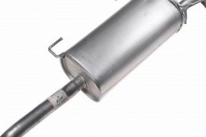
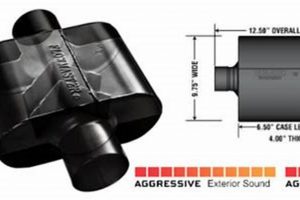
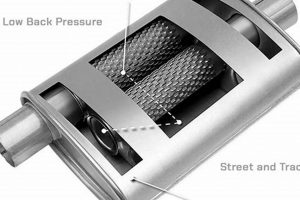
This device is a component designed to reduce noise generated by aircraft engines. Operating on principles of sound wave interference and absorption, it effectively minimizes the acoustic energy emitted into the environment. For example, the incorporation of such a device in aircraft significantly lowers the sound levels experienced by communities near airports.
Its importance stems from the growing need for noise pollution control, particularly around airports. The benefits include improved community relations, adherence to noise regulations, and a more comfortable environment for both passengers and ground personnel. Historically, these devices have evolved from simple baffle systems to sophisticated multi-stage units utilizing advanced materials and designs.
The following sections will delve into the specific mechanisms by which these units achieve noise reduction, the various design considerations involved in their construction, and the materials employed to optimize their performance under extreme operating conditions. Furthermore, an analysis of the current trends and future advancements in this field will be provided.
Tips for Effective Aircraft Noise Reduction
The following recommendations aim to optimize the selection, installation, and maintenance of components crucial for diminishing noise emanating from aircraft. Proper implementation of these guidelines will contribute to compliance with noise regulations and improved community relations.
Tip 1: Select Units Based on Engine Specifications: Choosing a unit that aligns with the specific engine type and operating parameters is paramount. An undersized or improperly matched unit will not deliver the intended noise reduction, leading to ineffective operation and potential engine damage.
Tip 2: Prioritize Material Durability: Given the harsh operating environment, selecting units constructed from high-temperature alloys and corrosion-resistant materials is crucial. This ensures longevity and consistent performance throughout the lifespan of the aircraft.
Tip 3: Implement Regular Inspection Schedules: Consistent monitoring for signs of wear, damage, or degradation is essential for maintaining optimal performance. Identifying and addressing issues early on prevents further complications and costly repairs.
Tip 4: Ensure Proper Installation Techniques: Adhering strictly to the manufacturer’s installation guidelines is critical. Improper installation can compromise the unit’s effectiveness and potentially introduce safety hazards.
Tip 5: Optimize Flow Path Design: The internal design of the unit should facilitate smooth airflow, minimizing backpressure and maximizing acoustic attenuation. Consult with experts in fluid dynamics to ensure optimal flow characteristics.
Tip 6: Invest in Advanced Acoustic Modeling: Utilizing sophisticated software to simulate noise propagation patterns and optimize the unit’s design can significantly enhance its effectiveness. This allows for precise tailoring to specific aircraft configurations.
Tip 7: Implement Noise Monitoring Programs: Establishing a comprehensive noise monitoring program around the airport provides valuable data for assessing the effectiveness of noise reduction measures and identifying areas for improvement.
By adopting these strategies, stakeholders can significantly reduce the impact of aircraft noise, fostering a more sustainable and harmonious relationship between aviation and the surrounding communities. Consistent adherence to these principles promotes operational efficiency and minimizes environmental concerns.
The subsequent sections will examine the legal framework governing aircraft noise emissions and explore emerging technologies that promise further advancements in noise reduction capabilities.
1. Sound wave attenuation
Sound wave attenuation is the fundamental principle upon which the efficacy of any device designed to reduce noise, particularly those integrated into aircraft propulsion systems, relies. Its effective implementation is paramount to achieving desired noise reduction levels and meeting regulatory compliance.
- Absorption Mechanisms
Attenuation is achieved through a combination of absorptive and reactive elements within the device. Absorptive materials, such as fiberglass or specialized foams, convert acoustic energy into heat, thereby reducing the amplitude of the sound waves. Reactive elements, such as baffles and resonators, manipulate the sound waves through interference, causing them to cancel each other out. The precise balance between these mechanisms is crucial for optimal performance across a broad frequency spectrum.
- Frequency-Specific Attenuation
Different frequencies of sound require different attenuation strategies. Lower frequencies are more difficult to attenuate due to their longer wavelengths, necessitating larger and more complex designs. Higher frequencies, on the other hand, are more readily absorbed by porous materials. Effective design necessitates a comprehensive understanding of the frequency characteristics of the engine’s noise output and the selection of appropriate attenuation techniques for each frequency range.
- Impact of Material Properties
The materials used in the construction of the device significantly influence its attenuation capabilities. Density, porosity, and flow resistivity are key material properties that affect sound absorption. High-density materials provide greater sound reflection, while porous materials facilitate sound absorption. Flow resistivity dictates the ease with which air can pass through the material, influencing its ability to dissipate acoustic energy. Selecting materials with the appropriate combination of these properties is essential for maximizing attenuation performance.
- Effect of Geometry and Configuration
The geometry and internal configuration of the device play a critical role in directing and manipulating sound waves. Baffles, strategically positioned within the device, create reflective surfaces that cause sound waves to interfere destructively. Resonators, tuned to specific frequencies, amplify and then cancel out unwanted noise components. The optimal configuration depends on the engine’s specific noise characteristics and the desired noise reduction levels. Computational fluid dynamics (CFD) simulations are often used to optimize the geometry and configuration for maximum attenuation.
The interplay of these factors underscores the complexity inherent in designing effective noise reduction systems for aircraft. Maximizing sound wave attenuation requires a holistic approach that considers material properties, geometric configuration, and the specific acoustic characteristics of the engine. Continual advancements in materials science and computational modeling are driving the development of more efficient and compact devices, enabling quieter and more sustainable aviation operations.
2. Engine compatibility range
The engine compatibility range represents a critical design parameter influencing the selection and performance of a device intended to reduce noise emissions from aircraft. Mismatched components lead to suboptimal noise reduction, potential engine damage, and non-compliance with regulatory standards. The range encompasses a spectrum of engine characteristics that must be carefully considered.
- Exhaust Gas Flow Rate
The volume of exhaust gas flowing through the system per unit of time directly impacts the selection criteria. Insufficient capacity within the device leads to increased backpressure, reducing engine efficiency and potentially causing overheating. Conversely, an oversized unit reduces noise reduction effectiveness. Manufacturers specify flow rate ranges within which optimal performance is achieved. Aircraft type and engine model directly determine the exhaust gas flow rate requirements.
- Exhaust Gas Temperature
Exhaust gas temperature fluctuates based on engine operating conditions, ranging from idle to maximum thrust. The materials used in the construction of the device must withstand these temperature variations without degradation or failure. High-temperature alloys and specialized ceramics are often employed to ensure durability and longevity. Exceeding the material’s temperature limit results in structural damage and compromised noise reduction performance.
- Engine Backpressure Limits
The addition of a noise reduction device inevitably introduces some level of backpressure on the engine. Exceeding the engine manufacturer’s specified backpressure limits results in reduced power output, increased fuel consumption, and potential engine damage. The internal design of the device must minimize backpressure while maximizing noise attenuation. Pressure drop calculations are essential to ensure compatibility.
- Acoustic Frequency Spectrum
The acoustic frequency spectrum generated by the engine varies depending on engine type and operating conditions. The internal design of the device must be tuned to effectively attenuate the dominant frequencies within this spectrum. Broadband attenuation is often desirable, but specific frequency ranges may require targeted treatment. Acoustic modeling and testing are crucial for optimizing performance across the relevant frequency spectrum.
The factors outlined above highlight the complex interdependencies that exist between engine characteristics and the design considerations for an aircraft noise reduction device. Proper matching ensures operational efficiency, regulatory compliance, and the desired reduction in noise pollution. A thorough understanding of the engine compatibility range is therefore indispensable for successful implementation.
3. Material heat resistance
Material heat resistance is a critical attribute directly influencing the performance and longevity of a device employed for aircraft noise reduction. The extreme thermal environment within aircraft exhaust systems necessitates materials capable of withstanding high temperatures without degradation. A device’s effectiveness is directly tied to its ability to maintain structural integrity and acoustic properties under prolonged exposure to these conditions. For instance, the failure of internal components due to thermal stress can lead to increased noise emissions and potential safety hazards. Inconel alloys, known for their high-temperature strength and corrosion resistance, are often utilized in the construction of such units to mitigate these risks.
The design and material selection processes for a component meant to reduce aircraft noise must account for the expected operating temperatures and thermal gradients. Computational fluid dynamics (CFD) simulations are often employed to predict temperature distributions within the device, enabling engineers to identify potential hotspots and optimize material selection accordingly. Furthermore, rigorous testing protocols are implemented to validate the thermal performance of the design under simulated operating conditions. For example, a prototype might undergo cyclic thermal testing, where it is repeatedly exposed to extreme temperature variations, to assess its resistance to thermal fatigue and creep.
Ultimately, material heat resistance is an indispensable factor in ensuring the reliable and effective operation of devices designed for aircraft noise reduction. Its consideration from the initial design phase through manufacturing and testing guarantees compliance with noise regulations, extends the lifespan of the component, and contributes to the overall safety and efficiency of aircraft operations. Overlooking this aspect can lead to premature failure, increased noise pollution, and elevated maintenance costs, underscoring its significance in the context of aviation engineering.
4. Airflow path optimization
Airflow path optimization is an integral component in the design and performance of aircraft noise reduction devices. This optimization directly affects the efficiency of sound wave attenuation and minimizes the imposition of backpressure on the aircraft engine. An inefficient airflow path leads to increased backpressure, reducing engine performance and potentially increasing fuel consumption, thereby negating the intended benefits of noise reduction. For example, a device with poorly designed internal baffles can create turbulent airflow, increasing backpressure and diminishing the effectiveness of sound absorption.
The design process involves computational fluid dynamics (CFD) simulations to model and analyze airflow patterns within the device. These simulations allow engineers to identify areas of high turbulence or stagnation, which can then be modified to streamline airflow and reduce backpressure. Real-world examples include the implementation of carefully contoured diffuser sections within the device, which gradually expand the flow area and reduce velocity, minimizing pressure losses. Also, the strategic placement of perforated plates or flow straighteners helps to homogenize the airflow and reduce turbulence. These techniques collectively contribute to enhancing the noise reduction capabilities without compromising engine performance.
Ultimately, effective airflow path optimization within a noise reduction device represents a critical engineering challenge. The correct balance between sound attenuation and minimal backpressure ensures the device functions as intended, providing effective noise reduction without negatively impacting aircraft performance or efficiency. Continuous refinement of airflow path design, aided by advanced modeling and simulation techniques, remains a crucial area of focus in the pursuit of quieter and more fuel-efficient aircraft operations.
5. Regulatory compliance mandates
Regulatory compliance mandates directly influence the design, implementation, and operational characteristics of aircraft noise reduction devices. These mandates, established by governing bodies such as the Federal Aviation Administration (FAA) and the International Civil Aviation Organization (ICAO), set permissible noise levels for aircraft operations, particularly in proximity to airports. Failure to comply results in substantial penalties, operational restrictions, and reputational damage for airlines and aircraft manufacturers. Therefore, these mandates act as the primary driving force behind the incorporation of noise reduction technologies into aircraft designs. An example is the Stage 4 noise standards, which necessitate significant noise reductions compared to previous generations of aircraft, prompting the development and adoption of advanced device designs.
The importance of regulatory compliance is further underscored by the stringent certification processes required for aircraft. These processes involve rigorous testing and analysis to demonstrate adherence to noise limits. For aircraft, this means demonstrating that the implemented noise reduction technologies, function effectively under various operating conditions. Non-compliance during certification leads to the rejection of the aircraft type, rendering it commercially unviable. Consequently, aircraft manufacturers invest heavily in research and development to ensure their designs meet or exceed regulatory requirements. For instance, advanced acoustic modeling techniques and sophisticated testing facilities are employed to optimize the noise reduction performance of these devices during the design phase.
In summary, regulatory compliance mandates serve as the foundation for the development and deployment of aircraft noise reduction technologies. These mandates not only define the permissible noise levels but also dictate the standards and procedures for aircraft certification. By enforcing these standards, regulatory bodies contribute to minimizing noise pollution and improving the quality of life for communities surrounding airports. Understanding the intricate relationship between regulatory mandates and the design of these devices is crucial for stakeholders in the aviation industry, including aircraft manufacturers, airlines, and regulatory agencies.
Frequently Asked Questions
This section addresses common inquiries regarding components used to minimize aircraft noise, providing concise and factual answers to promote understanding.
Question 1: What primary mechanism does a device for aircraft noise reduction utilize to attenuate sound?
The primary mechanisms involve sound wave interference and absorption. Interference achieves noise reduction through the superposition of sound waves to create destructive interference, canceling out specific frequencies. Absorption uses materials to convert sound energy into heat, reducing the overall sound pressure level.
Question 2: What are the typical materials used in the construction of aircraft noise reduction devices?
Common materials include high-temperature alloys such as Inconel, titanium, and stainless steel, chosen for their ability to withstand extreme temperatures and corrosive environments. Acoustic absorption materials like fiberglass, ceramic composites, and specialized foams are also employed.
Question 3: How does the design of the reduce noise influence engine performance?
The internal design seeks to minimize backpressure on the engine while maximizing sound attenuation. Excessive backpressure reduces engine efficiency, increases fuel consumption, and potentially damages engine components. Computational fluid dynamics (CFD) simulations are employed to optimize designs for minimal backpressure.
Question 4: What regulatory standards govern the use of noise reduction on aircraft?
Regulatory standards are primarily set by the Federal Aviation Administration (FAA) in the United States and the International Civil Aviation Organization (ICAO) globally. These standards define permissible noise levels for aircraft operations and mandate compliance through certification processes.
Question 5: How is the effectiveness of a measured?
Effectiveness is typically measured in decibels (dB) of noise reduction achieved. Standardized testing procedures are used to quantify noise levels before and after implementation of the device under various operating conditions. These measurements are then compared against regulatory limits.
Question 6: What maintenance procedures are required for aircraft used for noise reduction?
Regular inspections for damage, corrosion, and wear are essential. Replacement of worn or damaged components, especially absorption materials, ensures continued effectiveness. Adherence to manufacturer-specified maintenance schedules is crucial for optimal performance and safety.
These FAQs provide a foundational understanding of aircraft noise reduction components, addressing key design considerations, regulatory aspects, and maintenance requirements.
The following section will explore emerging technologies and future trends in the field of aircraft noise mitigation.
Conclusion
The preceding discussion has presented a comprehensive overview of the aero muffler. The functionality, design considerations, materials, and regulatory landscape governing these critical components were examined. The necessity of balancing noise reduction with engine performance and adherence to stringent mandates has been underscored. These systems are pivotal in mitigating noise pollution emanating from aircraft, directly influencing the quality of life for communities near airports.
Continued advancements in materials science, computational modeling, and acoustic engineering will undoubtedly drive further improvements in aero muffler technology. It is imperative that stakeholders in the aviation industry remain committed to investing in research and development in this field to facilitate a more sustainable and environmentally responsible future for air travel. The integration of these technologies is not merely a matter of compliance but a fundamental responsibility towards minimizing the impact of aviation on the global environment.


