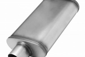
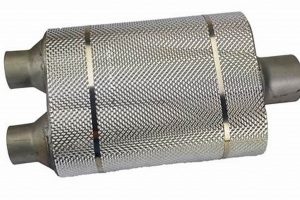
A device designed to reduce noise generated by airflow within a ventilation system is a critical component in maintaining acoustic comfort. These components, often constructed from sound-absorbing materials and strategically shaped to disrupt sound waves, are installed within the ductwork. For example, in a recording studio, these devices ensure that HVAC system operation doesn’t interfere with sensitive audio recording.
The use of these systems offers several benefits, including reduced noise pollution, improved speech intelligibility, and enhanced overall environmental quality. Historically, such noise control solutions were initially developed for industrial applications with high noise levels. Their application has gradually expanded to include residential, commercial, and institutional buildings where quiet environments are highly valued.
The following sections will delve into the specific types of these sound-attenuating elements, their design considerations, and the methods used to evaluate their performance. Attention will also be given to installation best practices and relevant industry standards for these products.
Optimizing Noise Reduction in Ventilation Systems
The following tips provide guidance on effectively integrating and utilizing noise reduction elements within air distribution networks to achieve optimal acoustic performance.
Tip 1: Proper Sizing is Crucial: Accurate duct sizing, based on airflow requirements and acceptable pressure drop, minimizes turbulence and subsequent noise generation. Overly restrictive ductwork creates excessive noise regardless of noise attenuation devices.
Tip 2: Strategic Placement Matters: Positioning the device close to the noise source, such as a fan or a sharp bend in the ductwork, maximizes its effectiveness. Analyze the duct layout and identify primary noise sources.
Tip 3: Consider System Effect: Account for the impact of the device on the overall system performance. Increased pressure drop can affect airflow rates and energy consumption. Select the model that balances noise reduction with system efficiency.
Tip 4: Utilize Acoustic Linings: Supplement the primary noise control device with internal duct linings to absorb sound waves and further reduce noise transmission. Ensure the lining material is appropriate for the intended environment and airflow velocity.
Tip 5: Implement Vibration Isolation: Address vibration transmitted through the ductwork by using vibration isolators between the fan unit and the duct system. This prevents structural borne noise from entering the ventilation network.
Tip 6: Regular Inspection and Maintenance: Periodically inspect and maintain the device to ensure it remains free of obstructions and that the acoustic material retains its sound-absorbing properties. Replace worn or damaged components as needed.
Tip 7: Prioritize Low-Frequency Attenuation: Pay particular attention to low-frequency noise, which can be more difficult to control. Select a model specifically designed for low-frequency noise reduction if this is a primary concern.
Effective implementation of these noise control techniques minimizes noise pollution, enhances acoustic comfort, and optimizes the performance of air distribution systems.
The following sections will explore case studies and advanced acoustic treatment strategies for complex ventilation systems.
1. Attenuation Performance
Attenuation performance is a fundamental metric in assessing the effectiveness of a ventilation sound attenuation device. It quantifies the degree to which the device reduces noise transmission through the ductwork, directly influencing the acoustic comfort of the occupied space. Proper attenuation ensures minimal disruption from HVAC system noise.
- Insertion Loss Measurement
Insertion loss is a primary method for evaluating attenuation performance. It measures the difference in sound power levels before and after the device is installed. A higher insertion loss value indicates greater noise reduction capability. This measurement is typically performed across a range of frequencies to characterize the device’s effectiveness at different sound wavelengths. For instance, a device with a high insertion loss at low frequencies is particularly effective at reducing rumble from fans.
- Frequency-Specific Attenuation
Attenuation performance varies across the frequency spectrum. Some devices are more effective at attenuating high-frequency noise, while others excel at reducing low-frequency sound. The design of the device, including its internal geometry and the type of sound-absorbing material used, dictates its frequency-specific attenuation characteristics. Analyzing frequency-specific data ensures the selected solution effectively addresses the dominant noise frequencies present in the ventilation system.
- Dynamic Insertion Loss
Static insertion loss measurements, conducted in laboratory settings, may not fully reflect real-world performance. Dynamic insertion loss considers the effects of airflow on the device’s acoustic performance. Airflow can affect the sound-absorbing properties of the material and alter the way sound waves propagate through the device. Dynamic measurements provide a more accurate assessment of attenuation performance under actual operating conditions.
- Impact of Upstream/Downstream Components
The components before and after the device in the ventilation system affect attenuation performance. Elbows, transitions, and other duct features can create turbulence and regenerate noise, negating some of the device’s effectiveness. Similarly, the acoustic properties of the downstream ductwork impact how effectively noise is contained. Optimal attenuation performance requires a holistic approach, considering the entire duct system configuration and acoustic environment.
The aforementioned components are essential to selecting a solution. Understanding insertion loss measurements, analyzing frequency-specific data, accounting for dynamic effects, and considering the impact of ductwork components contributes to ensure informed decisions. Evaluating these properties contributes to ensure efficient system integration and optimal noise reduction in ventilation systems.
2. Pressure Drop
Pressure drop, the reduction in static pressure of air as it moves through a duct system, is a critical consideration when integrating a ventilation sound attenuation device. The introduction of any obstruction into the airflow path will inevitably increase resistance, resulting in pressure loss. Understanding and managing this impact is crucial for maintaining system efficiency and performance.
- Relationship to Acoustic Performance
A trade-off often exists between acoustic performance and pressure drop. Designs that maximize sound attenuation frequently introduce more significant airflow resistance. The internal geometry, the density of the sound-absorbing material, and the overall length of the device all influence this relationship. Selecting the optimal device involves balancing the desired level of noise reduction with acceptable pressure drop limits.
- Impact on Fan Energy Consumption
Increased pressure drop across a ventilation sound attenuation device directly affects fan energy consumption. To maintain the required airflow rate, the fan must work harder to overcome the added resistance, leading to increased energy usage and higher operating costs. System designers must carefully consider pressure drop characteristics to minimize the energy penalty associated with noise control measures.
- System Design Implications
Accurate pressure drop calculations are essential during the ventilation system design phase. Undervaluing pressure drop can lead to insufficient airflow, resulting in inadequate ventilation and potential comfort issues. Conversely, overestimating pressure drop can lead to oversizing the fan, increasing initial costs and energy consumption. Detailed analysis, including computational fluid dynamics (CFD) modeling, may be necessary for complex systems.
- Mitigation Strategies
Several strategies can mitigate the negative impacts of pressure drop. Selecting devices with streamlined internal designs, minimizing the length of the device, and utilizing low-resistance sound-absorbing materials can all reduce pressure losses. Implementing variable frequency drives (VFDs) on fans allows for precise airflow control and energy optimization, even with increased pressure drop.
The management of pressure drop is an integral part of the design and implementation of ventilation sound attenuation. A thorough understanding of its relationship to acoustic performance, fan energy consumption, and overall system design is essential for achieving optimal results. Employing effective mitigation strategies ensures that noise control measures do not compromise system efficiency or performance.
3. Material Composition
Material composition is a defining characteristic influencing the performance and longevity of a ventilation sound attenuation device. The materials employed directly impact the device’s ability to absorb sound energy, its resistance to environmental factors, and its overall contribution to indoor air quality. A device’s effectiveness in reducing noise is intrinsically linked to the properties of its constituent materials. For instance, fiberglass, a common material, offers excellent sound absorption capabilities but may pose health concerns if fibers become airborne. Alternatively, mineral wool provides similar acoustic benefits with improved fire resistance and reduced risk of particle emission. The choice of material significantly affects the final product’s acoustic efficiency and safety profile.
The durability of a ventilation sound attenuation device is further determined by its material composition. In demanding environments, such as industrial settings with high humidity or chemical exposure, materials must exhibit resistance to degradation. Galvanized steel or aluminum are often used for the outer casing to prevent corrosion, while interior components may require specialized coatings or treatments to withstand specific environmental challenges. Proper material selection ensures the device maintains its structural integrity and acoustic performance over time, minimizing the need for frequent replacements and reducing maintenance costs. Furthermore, the material selection contributes to the overall indoor air quality. Devices incorporating antimicrobial treatments or low-VOC (Volatile Organic Compounds) materials prevent the growth of mold and bacteria and reduce the emission of harmful chemicals into the airstream. In sensitive environments, such as hospitals and laboratories, material composition is paramount to maintaining a healthy and safe indoor environment.
In summary, material composition is a critical factor in the design and selection of ventilation sound attenuation devices. The choice of materials influences acoustic performance, durability, and indoor air quality. A comprehensive understanding of these factors is essential for ensuring that the selected device effectively reduces noise pollution while maintaining a safe and healthy environment.
4. Size and Shape
The physical dimensions and configuration of ventilation sound attenuation devices are critical factors impacting their acoustic performance and integration within ductwork systems. These elements directly influence sound wave propagation and airflow characteristics, demanding careful consideration during design and selection.
- Attenuation Wavelength Compatibility
The dimensions of a sound attenuation device relative to the wavelengths of sound it is intended to attenuate are pivotal. Devices designed to reduce low-frequency noise typically require larger dimensions to effectively disrupt the longer sound waves. Conversely, smaller devices may suffice for high-frequency attenuation. Selection must align with the primary frequencies requiring reduction within the ventilation system.
- Ductwork Integration Constraints
The shape of the sound attenuation device must conform to the existing or planned ductwork configuration. Rectangular, circular, and oval shapes are common, each presenting distinct advantages and limitations in terms of airflow and installation space. In retrofit applications, space constraints may dictate the selection of a particular shape, potentially influencing achievable acoustic performance.
- Internal Geometry and Baffle Configuration
The internal geometry, including the arrangement of baffles or splitters, significantly impacts the device’s acoustic performance. Baffles redirect and absorb sound waves, increasing the path length and enhancing attenuation. The spacing, angle, and shape of baffles influence the device’s frequency-specific performance and pressure drop characteristics. Sophisticated designs optimize baffle configuration for broadband noise reduction while minimizing airflow resistance.
- Airflow Uniformity and Turbulence
The shape and internal design of a sound attenuation device can influence airflow uniformity and turbulence within the ductwork. Abrupt changes in cross-sectional area or poorly designed baffles can generate turbulence, increasing pressure drop and potentially creating additional noise. Streamlined designs with gradual transitions promote laminar airflow, minimizing these adverse effects and maximizing overall system efficiency.
The interplay between size and shape profoundly impacts the effectiveness and practicality of ventilation sound attenuation devices. Careful consideration of these factors, in conjunction with acoustic performance requirements and system constraints, is essential for achieving optimal noise control within ventilation systems.
5. Installation Location
The placement of a ventilation sound attenuation device, often referred to as an air duct muffler, is critical to its overall effectiveness in noise reduction. Its location within the ductwork directly impacts the device’s ability to intercept and attenuate sound waves generated by HVAC equipment or airflow turbulence. Proper placement considers proximity to noise sources, ductwork geometry, and the acoustic characteristics of the surrounding environment. For instance, installing the device close to a fan unit maximizes its ability to dampen fan noise before it propagates through the duct system. Conversely, locating it far from the noise source diminishes its effectiveness as sound waves may have already reflected within the ductwork, creating complex sound fields that are more difficult to control. The effectiveness of the component is compromised if the installation location is not correct.
In practice, the selection of an optimal location requires a comprehensive acoustic assessment of the ventilation system. This involves identifying primary noise sources, mapping sound pressure levels within the ductwork, and considering the potential for flanking paths where sound can bypass the device. Complex duct layouts with sharp bends or branches can create areas of increased turbulence and noise generation, necessitating strategic placement of the attenuation device to mitigate these effects. An example of good practice can be observed in recording studios or concert halls, where extensive acoustic modeling informs the precise positioning of sound attenuation devices to achieve optimal sound isolation and clarity. Careful evaluation of the intended installation spot is vital.
Ultimately, the installation location is not merely a logistical consideration but an integral component of the system’s performance. Suboptimal placement can render an otherwise effective sound attenuation device virtually useless, resulting in wasted resources and persistent noise problems. A thorough understanding of acoustic principles and careful planning are essential to ensure that the selected device is installed in a location that maximizes its noise reduction capabilities and contributes to a quiet and comfortable indoor environment. Correct location is just as important as the quality of the equipment in the system.
6. Duct Compatibility
The integration of a ventilation sound attenuation device into an existing or planned ductwork system is contingent upon its physical and performance compatibility with the ductwork’s characteristics. Mismatches between the device and the duct system can compromise acoustic performance, increase pressure drop, and even damage components.
- Dimensional Matching
The physical dimensions of the device must align with the ductwork’s size and shape. Incompatibility can create turbulent airflow, increasing noise and pressure drop. For example, a rectangular device installed in circular ductwork requires transition pieces, potentially adding to system complexity and acoustic inefficiency. Proper dimensional matching minimizes airflow disruptions.
- Material Compatibility
The materials of the device and the ductwork must be chemically compatible to prevent corrosion or degradation. Direct contact between dissimilar metals, such as aluminum and galvanized steel in humid environments, can lead to galvanic corrosion. Selection of compatible materials ensures long-term system integrity and prevents premature component failure.
- Pressure Class Rating
The device must be rated to withstand the static pressure within the ductwork. Exceeding the device’s pressure rating can cause structural failure and potential leakage. In high-pressure systems, reinforced devices with robust construction are necessary to maintain system integrity. Choosing a device with an appropriate pressure class rating is crucial for safe and reliable operation.
- Acoustic Impedance Matching
The device’s acoustic impedance should be matched to that of the ductwork to minimize sound reflections and maximize sound absorption. Mismatches in acoustic impedance can lead to standing waves and increased noise levels. Acoustic impedance matching involves careful consideration of the device’s materials, geometry, and placement within the duct system. Proper matching optimizes sound attenuation performance across the desired frequency range.
These considerations highlight the importance of duct compatibility. Addressing each element during the design and selection process optimizes its effectiveness, ensures long-term reliability, and reduces the risk of system failures.
7. Maintenance Needs
The operational lifespan and continued effectiveness of ventilation sound attenuation devices are directly linked to consistent and appropriate maintenance practices. Neglecting maintenance can lead to reduced acoustic performance, compromised air quality, and premature equipment failure. A structured maintenance plan ensures optimal functionality and extends the device’s service life.
- Inspection and Cleaning
Regular inspection of the device’s components is essential to identify potential issues such as accumulated dust, debris, or mold growth. These contaminants can impede airflow, reduce sound absorption, and compromise indoor air quality. Cleaning the device, typically involving vacuuming or wiping down surfaces with appropriate cleaning agents, removes these contaminants and restores optimal performance. Frequency depends on environmental conditions and air quality but should occur at least annually.
- Material Integrity Assessment
The sound-absorbing materials within the device can degrade over time due to moisture, temperature fluctuations, or chemical exposure. Periodic assessment of the material’s condition is necessary to identify signs of deterioration, such as sagging, crumbling, or discoloration. Replacement of damaged materials is crucial to maintain the device’s acoustic performance and prevent the release of harmful particles into the airstream.
- Structural Integrity Verification
The structural integrity of the device’s casing and support system must be verified to ensure safe and reliable operation. Corrosion, loose connections, or physical damage can compromise the device’s stability and potentially lead to collapse or detachment from the ductwork. Repairing or reinforcing damaged components is essential to prevent safety hazards and maintain system integrity.
- Airflow Measurement and Adjustment
Changes in the ventilation system’s airflow can impact the device’s acoustic performance and pressure drop characteristics. Periodic airflow measurements are necessary to verify that the device is operating within its design parameters. Adjustments to dampers or fan speed may be required to maintain optimal airflow and prevent excessive noise generation or energy consumption.
The consistent implementation of these maintenance procedures safeguards the performance and extends the lifespan of ventilation sound attenuation devices. Integrating maintenance into the broader HVAC system management plan ensures sustained acoustic comfort, improved air quality, and reduced operational costs.
Frequently Asked Questions about Ventilation Sound Attenuation
This section addresses common inquiries regarding noise reduction devices in air duct systems, providing concise and informative answers to enhance understanding and inform decision-making.
Question 1: What is the primary function of a ventilation sound attenuation device?
Its core purpose is to mitigate noise generated within ventilation systems, including fan noise, airflow turbulence, and equipment vibrations. By absorbing sound waves, these devices enhance acoustic comfort within occupied spaces.
Question 2: Where should it be installed within a ductwork system?
Optimal placement depends on the specific noise sources and ductwork configuration. Positioning the device close to the primary noise source, such as a fan or a sharp bend, is generally recommended. Acoustic analysis of the duct system helps determine the most effective location.
Question 3: How does it affect the overall airflow of a ventilation system?
Introducing such a device increases resistance to airflow, resulting in pressure drop. The pressure drop must be considered during system design to ensure adequate ventilation and avoid excessive fan energy consumption. Devices with streamlined designs minimize pressure drop.
Question 4: What materials are commonly used in their construction?
Common materials include fiberglass, mineral wool, and closed-cell foams for sound absorption, and galvanized steel or aluminum for the outer casing. Material selection depends on factors such as acoustic performance requirements, environmental conditions, and fire safety regulations.
Question 5: How can one determine if such a device is performing effectively?
Performance can be evaluated by measuring the sound pressure levels before and after installation using a sound level meter. Insertion loss measurements quantify the noise reduction achieved. Regular inspections ensure proper functionality and identify any degradation of acoustic materials.
Question 6: What maintenance is required to ensure the longevity of this equipment?
Regular maintenance includes inspection for dust and debris accumulation, cleaning to remove contaminants, and assessment of material integrity. Damaged components should be replaced promptly to maintain optimal acoustic performance and prevent potential health hazards.
In summary, understanding the function, installation, impact, materials, performance, and maintenance of these devices is essential for effective noise control in ventilation systems.
The subsequent section will delve into advanced acoustic modeling techniques used to optimize the placement and selection of sound attenuation devices in complex ventilation networks.
Air Duct Muffler
This examination has traversed the critical aspects of the air duct muffler, encompassing its function, design considerations, installation protocols, and maintenance imperatives. The analysis underscores the vital role these components play in achieving acoustic comfort within diverse environments. From selecting appropriate materials to optimizing placement and ensuring compatibility with existing ductwork, each decision point profoundly impacts the system’s overall performance and effectiveness. Considerations of pressure drop, frequency-specific attenuation, and long-term material integrity are paramount for successful implementation.
The future of ventilation system design demands a rigorous application of acoustic principles and a commitment to sustainable practices. Investment in advanced modeling techniques and proactive maintenance strategies will further enhance the performance and longevity of noise attenuation solutions. By prioritizing informed selection and meticulous upkeep, stakeholders can ensure quieter, healthier, and more productive indoor environments, reinforcing the significance of the air duct muffler as an indispensable element of modern building infrastructure.


