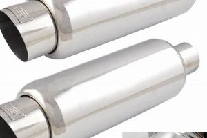
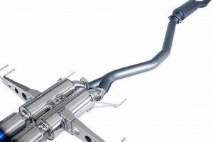
A technical illustration detailing the internal construction of a device designed to reduce the noise emitted from an engine’s combustion process. This illustration typically shows the various chambers, baffles, and pathways through which exhaust gases travel. For example, such a drawing might depict a cross-sectional view, highlighting the gas flow and sound wave dissipation mechanisms within the component.
These schematics are essential for understanding the functionality and optimizing the performance of automotive exhaust systems. They enable engineers and technicians to diagnose issues, design more effective noise reduction strategies, and ensure compliance with noise pollution regulations. Historically, these illustrations have evolved from hand-drawn blueprints to sophisticated computer-aided designs, reflecting advancements in both automotive engineering and drafting technology.
Further discussion will elaborate on the different types of mufflers, the principles of sound attenuation they employ, and the role these illustrations play in their development and maintenance.
Guidance on Utilizing Schematics of Exhaust Noise Reduction Devices
The following points offer guidance for effectively using technical drawings that represent the internal workings of devices designed to mitigate engine exhaust noise.
Tip 1: Understand the Legend: Before interpreting the illustration, carefully review the legend. It defines symbols, materials, and measurement units used throughout the drawing, ensuring accurate comprehension of the represented components.
Tip 2: Analyze Gas Flow Pathways: Trace the represented route of exhaust gases through the internal chambers and baffles. This allows for an understanding of how the device reduces sound waves by altering their direction and velocity.
Tip 3: Identify Sound Attenuation Methods: Determine the noise reduction techniques employed within the device based on its internal construction. Absorption, reflection, and interference are common methods visible in the illustration.
Tip 4: Assess Material Specifications: Note the materials specified for different components. These specifications impact the device’s durability, heat resistance, and overall effectiveness in noise reduction.
Tip 5: Compare Different Designs: When evaluating multiple devices, use their respective schematics to compare and contrast their internal structures. This comparison aids in selecting the most suitable component for a specific application.
Tip 6: Use for Troubleshooting: When diagnosing performance issues, consult the appropriate illustration to identify potential points of failure or blockage within the device’s internal structure.
Tip 7: Verify Dimensions and Tolerances: Ensure that any modifications or repairs adhere to the specified dimensions and tolerances outlined in the illustrations to maintain optimal performance and prevent potential damage.
Properly interpreting these illustrations facilitates informed decision-making regarding selection, maintenance, and potential optimization of exhaust noise reduction systems.
The following sections will explore specific applications and considerations for various vehicle types and emission standards.
1. Component Identification
Illustrations of exhaust noise reduction devices necessitate precise component identification for effective interpretation and application. These schematics serve as visual dictionaries, where each element, such as baffles, chambers, inlets, and outlets, must be unambiguously recognized. A lack of proper identification renders the entire representation incomprehensible, preventing informed decision-making regarding maintenance, repair, or system optimization. For example, the inability to distinguish between a resonance chamber and a perforated tube within a diagram could lead to incorrect parts ordering or misguided modification attempts, ultimately compromising the system’s performance.
Detailed illustrations frequently incorporate labels, callouts, and material specifications alongside each component. This level of detail is critical for accurate diagnosis of malfunctions within the exhaust system. Consider a scenario where a technician uses a schematic to troubleshoot excessive noise. By correctly identifying a corroded baffle within the diagram, the technician can pinpoint the source of the problem and replace the specific component rather than undertaking a costly and unnecessary replacement of the entire system. Furthermore, component identification is crucial during the manufacturing and assembly stages, ensuring correct placement and orientation of internal components to meet the intended noise reduction specifications.
In conclusion, accurate component identification forms the bedrock for understanding and utilizing exhaust muffler diagrams effectively. Challenges related to misidentification or lack of detail in diagrams can lead to improper maintenance, compromised performance, and increased costs. Therefore, standardized nomenclature, clear labeling, and comprehensive diagrams are paramount for facilitating informed decision-making throughout the lifecycle of exhaust noise reduction systems. The capacity to properly identify components translates directly into enhanced system efficiency and regulatory compliance.
2. Gas Flow Paths
The configuration of gas flow paths within an exhaust muffler, as depicted in a technical illustration, is fundamental to its noise reduction capabilities. The design and arrangement of these pathways directly influence the attenuation of sound waves generated by the engine. Thus, the depiction of these paths is a primary feature of relevant schematics.
- Path Length and Complexity
The length and complexity of the gas flow path dictate the degree of sound wave attenuation. Longer and more convoluted paths force sound waves to travel further and undergo more reflections and interactions, thus dissipating energy. Technical illustrations will show the relative lengths of various internal passages. For example, a diagram might highlight an extended, serpentine pathway designed to maximize sound wave absorption.
- Chamber Design and Placement
The number, shape, and placement of internal chambers are crucial for controlling gas flow and sound wave interference. Resonance chambers, for instance, are designed to cancel out specific frequencies. Illustrations pinpoint the dimensions and locations of these chambers, demonstrating how they contribute to overall noise reduction. A schematic may display chambers strategically placed to disrupt sound waves traveling through the system.
- Baffle Configuration and Orientation
Baffles, internal partitions that redirect gas flow, are essential components within mufflers. Their design and orientation significantly impact sound wave reflection and diffusion. Schematics clearly illustrate the angle and spacing of baffles, revealing how they control the directional propagation of sound waves. Illustrations may show baffles angled to reflect sound waves back towards the engine, causing destructive interference.
- Perforation Patterns and Density
The presence and characteristics of perforated tubes or plates within the gas flow path contribute to sound absorption and redirection. The size, density, and arrangement of these perforations influence the frequency range that is most effectively attenuated. Illustrations detail the patterns and dimensions of these perforations. A schematic might include a close-up view of perforated tube, displaying the hole size and spacing, and the tube’s location within the system.
These elements, when accurately portrayed, allow for a comprehensive understanding of how specific system designs effectively mitigate engine noise. The proper interpretation of these diagrams is crucial for design optimization, troubleshooting, and the overall efficiency of exhaust systems.
3. Attenuation Techniques
Attenuation techniques, strategies employed to reduce sound intensity, are integrally represented within illustrations of exhaust noise reduction devices. A schematic provides a visual inventory of these methods, showcasing how design elements contribute to the suppression of noise. For instance, a reactive muffler leverages interference principles, with chambers precisely dimensioned to reflect and cancel specific sound frequencies. The diagram delineates these chambers, their volumes, and the connecting pipe lengths, providing critical data to assess the muffler’s effectiveness at targeting particular frequencies. Absorptive mufflers, conversely, rely on sound-absorbing materials such as fiberglass packing. The illustration specifies the quantity, placement, and density of this material, which correlates directly with the muffler’s ability to dampen sound energy across a broader frequency spectrum. Real-world examples include performance vehicle mufflers employing both reactive and absorptive techniques to balance noise reduction with minimal backpressure, where the schematic outlines the integrated system.
Further analysis reveals the significance of diagrammatic representation for troubleshooting and optimization. Consider a scenario where a muffler exhibits reduced noise reduction effectiveness. The illustration allows a technician to examine the internal structure for damage, such as a collapsed baffle or degraded absorptive packing. The diagram’s dimensional details aid in verifying that internal components conform to design specifications, ruling out manufacturing defects or unauthorized modifications. Similarly, engineers use these illustrations during design iterations to model and optimize gas flow dynamics, chamber volumes, and baffle configurations, leveraging computational fluid dynamics (CFD) to predict noise reduction performance. For example, the illustration allows a designer to see the path exhaust gases travel, allowing the designer to modify the design so gases will travel longer, reducing noise produced by the exhaust.
In summary, the link between sound attenuation techniques and technical illustrations of exhaust noise reduction devices is essential for understanding the operation, diagnosing problems, and improving the design of these systems. Challenges lie in creating accurate and detailed schematics that capture the complex interactions of sound waves within the muffler. The ability to interpret these illustrations effectively contributes to enhanced vehicle noise control, regulatory compliance, and improved overall vehicle performance.
4. Material Composition
The selection of materials for exhaust noise reduction devices, as indicated within a schematic, significantly influences the system’s performance, durability, and compliance with environmental regulations. These illustrations provide essential information regarding the composition of components, impacting heat resistance, corrosion resistance, and acoustic properties.
- Steel Alloys and Corrosion Resistance
Various steel alloys are commonly used in muffler construction, each offering differing levels of corrosion resistance. Schematics often specify the grade of stainless steel or aluminized steel used, indicating the component’s ability to withstand exposure to exhaust gases, moisture, and road salts. For example, a diagram might indicate 304 stainless steel for the muffler body, offering superior corrosion protection compared to aluminized steel, which may be used for internal baffles. This distinction in material selection directly impacts the lifespan of the system.
- Acoustic Absorption Materials
Illustrations detail the type and quantity of acoustic absorption materials used, such as fiberglass packing or ceramic wool. These materials are critical for dampening sound waves within the muffler. The diagram will specify the material density and placement, influencing the frequency range that is most effectively attenuated. For instance, a performance muffler diagram might show a high-density ceramic wool packing designed to absorb high-frequency sounds, whereas a standard muffler may use a less dense fiberglass packing more suited for lower frequencies.
- Weld Quality and Material Compatibility
The method and materials used for welding different components together are integral to the system’s structural integrity. Diagrams may include notes on welding specifications, ensuring compatibility between dissimilar metals and preventing galvanic corrosion. For example, a diagram might specify a TIG welding process for joining stainless steel components to prevent carbon steel contamination, which can lead to premature corrosion at the weld joints. Proper material selection and welding techniques ensure the system remains structurally sound under high temperatures and vibrational stresses.
- Catalytic Converter Substrate Material
For systems incorporating a catalytic converter, the diagram specifies the substrate material, typically a ceramic or metallic honeycomb structure coated with catalytic agents. The composition of the substrate influences its thermal stability and resistance to chemical degradation. Illustrations may detail the cell density and material composition, affecting the converter’s efficiency in reducing harmful emissions. A diagram might note a platinum-rhodium coating on a ceramic substrate, indicating its ability to catalyze the oxidation of hydrocarbons and carbon monoxide and the reduction of nitrogen oxides.
In conclusion, a thorough understanding of the material composition, as delineated within illustrations of exhaust noise reduction devices, is essential for assessing system performance, predicting longevity, and ensuring compliance with environmental regulations. The accurate depiction of these materials contributes to informed decision-making during design, manufacturing, and maintenance processes.
5. Dimensional Accuracy
Dimensional accuracy in an illustration of an exhaust noise reduction device is not merely a matter of aesthetic precision; it constitutes a fundamental prerequisite for the effective design, manufacturing, and maintenance of the system. Inaccurate dimensions within a diagram can propagate errors throughout the entire lifecycle of the component, from initial prototyping to aftermarket repairs. Discrepancies between the illustrated dimensions and the actual physical dimensions can lead to improper fitment, reduced performance, and, in extreme cases, system failure. For example, if the diameter of an inlet pipe is incorrectly depicted, a technician may order the wrong size replacement part, resulting in a compromised seal and exhaust leakage. A precise drawing serves as the master reference for all downstream activities.
The practical significance of dimensional accuracy extends beyond basic component fitment. The internal geometry of an exhaust system, particularly the dimensions of resonant chambers and baffle placements, is critical for achieving targeted noise reduction. Even minor dimensional deviations can significantly alter the system’s acoustic properties, potentially leading to non-compliance with noise emission regulations. Furthermore, dimensional accuracy is crucial for validating computational fluid dynamics (CFD) simulations used in muffler design. These simulations rely on precise geometric data to accurately predict gas flow and acoustic behavior. If the dimensions used in the simulation are inaccurate, the simulation results will be unreliable, hindering the optimization of the muffler’s design. Cases of improperly manufactured mufflers due to misinterpretations of schematic dimensions have highlighted the cost implications of inaccurate illustrations, including production delays and product recalls.
In conclusion, dimensional accuracy forms the bedrock upon which the reliability and effectiveness of exhaust noise reduction systems are built. Ensuring precision in these illustrations necessitates rigorous quality control measures throughout the drafting process, including the use of calibrated measuring instruments and adherence to established drafting standards. Challenges persist in maintaining accuracy when transitioning between different design platforms or when converting legacy drawings to digital formats. However, the consequences of dimensional inaccuracies are sufficiently severe to warrant diligent attention to detail and the implementation of robust validation procedures, solidifying accurate depictions as a cornerstone of compliant, high-performance exhaust systems.
6. Design Variations
The diverse range of designs for exhaust noise reduction devices necessitates detailed illustrative documentation. These variations arise from differing engine characteristics, vehicle applications, and noise emission standards, each requiring specific internal configurations. A comprehensive depiction of these designs is thus critical for understanding their functionality and application.
- Chamber Configuration and Resonance Frequency Tuning
Variations in chamber size, shape, and interconnectivity create distinct resonance frequencies, tailored to attenuate specific engine noise profiles. A schematic illustration highlights these dimensions, allowing for the identification of targeted frequency ranges and the assessment of overall noise reduction effectiveness. Examples include designs optimized for low-frequency rumble in diesel engines versus high-frequency whine in gasoline engines. The illustration acts as a key for understanding how geometric parameters translate to acoustic performance.
- Baffle Arrangement and Flow Impedance
The arrangement of internal baffles dictates the flow path of exhaust gases, influencing backpressure and noise attenuation. Designs range from simple, straight-through configurations to complex, multi-chamber arrangements with convoluted flow paths. The corresponding illustration clearly depicts baffle placement, angle, and perforation patterns, allowing for the assessment of flow impedance and its trade-off with noise reduction. The diagrams are essential for balancing performance and noise constraints.
- Acoustic Absorption Material Usage and Frequency Range
Variations in the type, density, and placement of acoustic absorption materials (e.g., fiberglass, steel wool) influence the frequency range of noise attenuation. Illustrations specify the material composition, thickness, and coverage area within the muffler, enabling evaluation of its effectiveness in dampening broadband noise. For instance, designs incorporating high-density materials target high-frequency noise, while those with less dense materials address lower frequencies. The diagrams facilitate the optimization of acoustic material usage.
- Overall Size and Packaging Constraints
Physical size constraints, dictated by vehicle chassis design and available space, significantly influence muffler design. Illustrations depict the overall dimensions and mounting points, demonstrating how internal components are packaged within the available volume. Compact designs often prioritize noise reduction through complex flow paths, while larger designs may incorporate larger chambers and more extensive absorption materials. These diagrams serve as a guide for proper installation and ensure compatibility with specific vehicle models.
In sum, these facets of design variation, as reflected in the illustrations of exhaust noise reduction devices, underscore the complexity involved in tailoring noise mitigation to specific applications. These representations function as blueprints, facilitating understanding, optimization, and maintenance of a diverse range of systems. These variations provide examples and comparisons on the main topic: exhaust muffler diagram.
Frequently Asked Questions
The following questions address common inquiries regarding the interpretation and utilization of schematics detailing exhaust noise reduction devices.
Question 1: What is the primary purpose of an exhaust muffler diagram?
The primary purpose is to provide a technical representation of the muffler’s internal construction, illustrating the arrangement of chambers, baffles, and pathways through which exhaust gases flow. This enables engineers, technicians, and manufacturers to understand the device’s operation, diagnose issues, and optimize its design.
Question 2: What key components are typically identified in these illustrations?
Key components include, but are not limited to, the inlet and outlet pipes, resonant chambers, baffles, perforated tubes, acoustic absorption materials (e.g., fiberglass packing), and any welding joints. Material specifications and dimensional tolerances are often indicated as well.
Question 3: How can these diagrams assist in troubleshooting exhaust system problems?
These diagrams allow technicians to visualize the internal structure and identify potential points of failure, such as corroded baffles, blocked pathways, or degraded absorption materials. This facilitates targeted repairs, minimizing unnecessary component replacements.
Question 4: Why is dimensional accuracy so crucial in these illustrations?
Dimensional accuracy is paramount for ensuring proper fitment of replacement parts, validating computational fluid dynamics (CFD) simulations, and maintaining the acoustic performance of the system. Deviations from specified dimensions can lead to reduced noise reduction and potential regulatory non-compliance.
Question 5: How do design variations in exhaust mufflers affect the corresponding diagrams?
Design variations reflect differences in engine characteristics, vehicle applications, and noise emission standards. These variations are manifested in the arrangement of internal components, chamber sizes, and the type and quantity of acoustic absorption materials. Diagrams must accurately depict these design differences.
Question 6: Where can reliable and accurate examples of these diagrams be found?
Accurate representations are typically found in manufacturer service manuals, engineering design documents, and specialized technical publications. Third-party sources may also provide illustrations, but their accuracy should be verified against official documentation.
A thorough understanding of these diagrams is crucial for maintaining exhaust systems and ensuring compliance with noise regulations.
The next section will detail practical applications and case studies related to muffler design and troubleshooting.
Exhaust Muffler Diagram
This exploration of the exhaust noise reduction device illustration has underscored its significance as a critical technical resource. The component identification, gas flow paths, attenuation techniques, material composition, dimensional accuracy, and design variations detailed within these schematics are fundamental to understanding, maintaining, and optimizing exhaust systems. The proper interpretation of such illustrations enables informed decision-making throughout the lifecycle of these essential automotive components.
Continued adherence to precise drafting standards and diligent application of these schematics will contribute to enhanced vehicle performance, regulatory compliance, and a reduction in noise pollution. The importance of these illustrations extends beyond the design and manufacturing phases, serving as a vital tool for ensuring the long-term effectiveness of exhaust noise reduction strategies. Further research and development in this area are essential for meeting increasingly stringent environmental regulations and improving the overall quality of life in urban environments.


