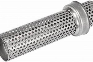
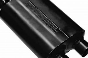
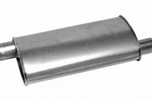
The placement of exhaust components intended to mitigate unwanted low-frequency sound within a vehicle’s exhaust system is a critical factor in their effectiveness. The position of a tuned device, relative to the primary noise reduction component, significantly influences its ability to cancel or attenuate these undesirable sound waves.
Optimizing the location of these elements can lead to a more pleasant and refined auditory experience within the vehicle cabin. Historically, experimentation and empirical data have guided the development of various configurations, aiming to minimize disturbance while maintaining optimal engine performance. The effectiveness is dependent on various aspects of the exhaust system design.
Therefore, understanding the properties of specific sound-canceling devices, and how their position impacts the overall sound profile, is key to achieving desired noise reduction. Considerations regarding engine characteristics, exhaust flow dynamics, and vehicle-specific attributes play a vital role in tailoring the system for optimum performance.
Placement Considerations for Exhaust System Tuning
Optimizing the placement of exhaust components is crucial for effectively mitigating undesirable low-frequency noise. Understanding the impact of component order can significantly enhance the sound quality produced by the exhaust system.
Tip 1: Analyze Frequency Characteristics: Before modifying the exhaust system, identify the specific frequencies causing the droning. This assessment dictates the necessary tuning to the exhaust system.
Tip 2: Prioritize Noise Reduction: Determine the primary goal maximum sound reduction or a balance between performance and sound quality. This informs the overall design choices.
Tip 3: Evaluate Space Constraints: Assess the available space under the vehicle to ensure the chosen components can be installed without compromising ground clearance or other mechanical systems. Consider the heat emitted from the exhaust system.
Tip 4: Consider Flow Dynamics: Changes to the exhaust system affect exhaust flow. Ensure that modifications do not restrict flow to the point of negatively impacting engine performance.
Tip 5: Test Multiple Configurations: Experiment with different placements to identify the most effective configuration for minimizing undesirable noise. Utilize sound measurement equipment for accurate evaluations.
Tip 6: Consult Exhaust Specialists: Seek expert advice from professionals experienced in exhaust system design and tuning. They can provide valuable insights and prevent costly mistakes.
Tip 7: Assess Engine Layout: The most effective resonator placement may differ by engine type and layout, and where drone is most prevalent.
Proper installation of exhaust components is essential to ensuring long term durability and peak performance. Take time to consider how these components interact and impact exhaust flow.
Implementing these strategies contributes to refining the exhaust note, creating a more pleasant and controlled auditory experience.
1. Frequency Attenuation
Frequency attenuation, the reduction of sound energy at specific frequencies, is a central concern when addressing exhaust drone through the strategic placement of resonators and mufflers. The effectiveness of an exhaust system in minimizing drone is directly related to its ability to target and diminish the problematic frequencies. Component placement influences this attenuation.
- Resonator Tuning and Target Frequencies
Resonators are designed to attenuate specific frequency ranges. The frequency at which a resonator is most effective is determined by its design and dimensions. Positioning a resonator before or after the muffler alters the frequency profile it encounters. For instance, if the muffler primarily addresses high frequencies, placing a resonator before it to target low-frequency drone may be beneficial. Conversely, if the muffler attenuates mid-range frequencies, positioning the resonator afterward may further refine the exhaust note by addressing remaining undesirable frequencies.
- Muffler Characteristics and Frequency Range
Mufflers attenuate sound across a broader frequency spectrum. Chambered mufflers, for example, reduce noise through sound wave cancellation within their internal chambers, while absorption mufflers utilize sound-absorbing materials. The effectiveness of a muffler varies with frequency. Placing a resonator upstream of a muffler can pre-condition the exhaust flow by reducing specific frequencies, allowing the muffler to operate more effectively within its optimal range.
- Exhaust Gas Temperature and Frequency
Exhaust gas temperature affects the speed of sound waves. Higher temperatures shift the frequency spectrum. Placing the resonator closer to the engine, where temperatures are higher, may alter its effective frequency range. Temperature considerations are important for precise tuning.
- System Harmonics and Resonance
Exhaust systems often exhibit resonant frequencies, creating harmonic drone. Resonators can be strategically placed to counter these resonant frequencies. If the primary resonance occurs after the muffler, placing a resonator downstream of the muffler to specifically target that frequency will yield the greatest reduction in drone.
In summary, achieving optimal frequency attenuation for drone reduction necessitates a thorough understanding of both the characteristics of the resonator and muffler, as well as the frequency profile of the exhaust noise itself. Careful consideration of component placement, factoring in exhaust gas temperature and system harmonics, results in a more effective and targeted approach to managing unwanted exhaust sound.
2. Exhaust Flow Dynamics
The characteristics of exhaust gas flow significantly influence the performance of noise-canceling components within an exhaust system. The strategic placement of a resonator relative to a muffler must account for these dynamics to effectively mitigate undesirable sound frequencies and avoid hindering engine performance.
- Backpressure Effects
Each component within the exhaust system introduces a degree of backpressure, which can affect engine efficiency. Restrictive mufflers or improperly sized resonators can impede exhaust flow, leading to reduced horsepower and torque. Placing a resonator before a muffler that already presents significant resistance can exacerbate backpressure issues, while placing it afterward may provide a slight buffer, minimizing the overall impact on engine performance. The cross-sectional area of the components needs to be engineered to balance noise reduction and flow resistance.
- Turbulence and Flow Uniformity
Exhaust gas flow is inherently turbulent, particularly after exiting the engine. Resonators and mufflers introduce further turbulence. Placing a resonator before a muffler can, in some cases, homogenize the exhaust flow, allowing the muffler to operate more effectively. However, it can also create additional turbulence, negating the intended benefit. Computational fluid dynamics (CFD) analysis is often employed to model and optimize flow uniformity.
- Gas Temperature and Density Variations
Exhaust gas temperature and density fluctuate throughout the exhaust system. Gas density is inversely proportional to its temperature. These variations influence the speed of sound and thus affect the frequencies that noise-canceling components target. A resonator’s effectiveness is partially dependent on gas temperature. Consideration is needed on the placement of a resonator so that it corresponds to the expected exhaust gas temperature.
Therefore, optimizing the arrangement involves balancing the acoustic benefits with the potential for adverse effects on exhaust flow. Careful consideration of component design, size, and placement, informed by computational modeling and empirical testing, is crucial for achieving both noise reduction and optimal engine performance. If exhaust flow changes dramatically, so will the noise generated and the appropriate location for noise-canceling components.
3. Spatial Constraints
Spatial constraints, the limitations imposed by the available physical space under a vehicle, exert a significant influence on the decision of component placement within the exhaust system. The dimensions of the vehicle’s undercarriage, the location of existing components such as the fuel tank, suspension elements, and drivetrain components, and the need to maintain adequate ground clearance directly affect the selection and positioning of noise reduction devices. The available area for a resonator and muffler dictate both their size and relative positions. For instance, in a compact vehicle with limited underbody space, a smaller resonator may be chosen and placed after the muffler due to the muffler’s typically larger size and more fixed location near the rear of the vehicle. This decision acknowledges that the effectiveness of this configuration might be slightly compromised compared to an ideal placement, but is necessary to accommodate the physical limitations.
Consider a sports car with a low ride height. Adding a large resonator before the muffler may reduce ground clearance to an unacceptable level, increasing the risk of damage from speed bumps or uneven road surfaces. In this scenario, a smaller, more compact resonator placed after the muffler, or a combination muffler-resonator component, may be the only viable solution. Alternatively, the exhaust piping might be rerouted to create additional space, but this adds complexity and cost. Another common constraint is the proximity of the exhaust system to heat-sensitive components, such as fuel lines or the vehicle’s underbody. Adequate heat shielding and airflow are essential to prevent damage, and this may further limit the available space for component placement. The geometry of the vehicle’s frame also influences the path of the exhaust system, forcing components to be placed in specific locations.
Ultimately, the successful integration of noise reduction measures requires a balance between acoustic performance and practicality. While theoretical models may suggest an optimal arrangement of components, real-world applications necessitate compromises dictated by the available space. A thorough assessment of spatial constraints is essential to ensure that the chosen configuration not only effectively mitigates undesirable sound but also maintains the vehicle’s functionality, safety, and durability. It is more beneficial to have an exhaust configuration that performs “good enough” and adheres to spatial constraints. The only real alternative to this is a custom solution with a matching price tag.
4. Component Synergies
Component synergies within an exhaust system describe the interactive and combined effects of individual elements working in concert to achieve a desired outcome, in this case, the reduction of unwanted low-frequency noise. The placement of a resonator relative to a muffler is central to optimizing these synergistic effects, as the order can dramatically influence the overall sound attenuation characteristics of the system.
- Frequency Range Division
The resonator and muffler can be selected and positioned to address different portions of the sound frequency spectrum. A resonator tuned to target a specific drone frequency, when placed upstream of a muffler, can reduce the amplitude of that frequency before it reaches the muffler. This allows the muffler to more effectively attenuate the remaining frequencies, improving overall noise reduction. Conversely, placing the resonator downstream allows it to fine-tune the exhaust note after the muffler has handled the broader frequency range.
- Wave Interference Exploitation
Resonators function by creating destructive interference of sound waves, canceling out specific frequencies. When strategically placed relative to the muffler, the reflected waves from the resonator can interact with the sound waves exiting the muffler. This interaction can lead to further noise reduction through constructive or destructive interference, depending on the phase relationship between the waves. The ideal placement maximizes destructive interference at the targeted drone frequencies.
- Flow Conditioning Effects
A resonator placed upstream of the muffler can act as a flow conditioner, reducing turbulence and creating a more uniform exhaust flow. This can improve the muffler’s performance by ensuring a more consistent interaction between the sound waves and the muffler’s internal structure. The placement can alter the temperature and composition of the gasses flowing through the devices.
- Backpressure Management
Each component adds backpressure to the exhaust system, potentially affecting engine performance. The combined backpressure of the resonator and muffler must be carefully managed. Placing the resonator strategically can influence the overall backpressure. For example, positioning a less restrictive resonator before a more restrictive muffler may result in better flow than if the order were reversed, minimizing the performance impact while still reducing drone.
In summary, component synergies are crucial for achieving effective drone reduction in an exhaust system. The optimal arrangement of a resonator and muffler requires a detailed understanding of frequency characteristics, wave interference, flow dynamics, and backpressure management. By carefully considering these factors, the combined performance of the system can be significantly enhanced, resulting in a more refined and desirable exhaust sound.
5. Harmonic Cancellation
Harmonic cancellation is a core principle in exhaust system design, especially when addressing undesirable drone frequencies. The strategic placement of a resonator relative to a muffler is dictated by the specific harmonic frequencies needing attenuation, directly influencing the effectiveness of drone reduction.
- Targeted Frequency Attenuation
Exhaust drone is often caused by resonant frequencies within the exhaust system. A resonator, acting as a Helmholtz resonator or a quarter-wave tube, is designed to cancel out specific frequencies. Placing the resonator before the muffler allows it to target these primary resonant frequencies, reducing their amplitude before they reach the muffler. This approach is beneficial when the dominant drone frequency is well-defined and consistent. For example, if a vehicle consistently exhibits drone at 120Hz, a resonator tuned to that frequency placed upstream can significantly reduce its impact.
- Broadband vs. Narrowband Attenuation
Mufflers generally provide broadband noise attenuation, reducing sound across a wider range of frequencies. Resonators, on the other hand, are more effective at narrowband attenuation, targeting specific frequencies. If the goal is to eliminate a specific harmonic frequency, placing the resonator after the muffler allows for fine-tuning of the exhaust note, removing any lingering drone frequencies not fully addressed by the muffler’s broadband attenuation. An example is removing a slight hum that remains after the muffler has reduced the overall exhaust noise.
- Phase Interference Optimization
Harmonic cancellation relies on creating destructive interference of sound waves. The resonator generates a sound wave that is out of phase with the problematic harmonic frequency, effectively canceling it out. The placement of the resonator influences the phase relationship between these waves. For optimal cancellation, the resonator should be positioned at a location where the phase difference between the original sound wave and the resonator’s generated wave is approximately 180 degrees at the target frequency. This precise placement often requires experimentation and acoustic analysis.
- System Resonance Modification
The addition of a resonator alters the overall resonant characteristics of the exhaust system. By carefully selecting the resonator’s size and placement, the system’s resonant frequencies can be shifted away from the engine’s operating range, thereby minimizing drone. Placing the resonator before the muffler can influence the resonant behavior of the muffler itself, potentially improving its overall noise reduction capabilities. This is especially useful in preventing harmonics from forming in the first place.
In conclusion, the placement of a resonator before or after the muffler for harmonic cancellation depends critically on the specific frequencies needing attenuation, the desired level of broadband versus narrowband noise reduction, the need for precise phase interference, and the overall modification of system resonance. A thorough understanding of these factors is essential for effectively mitigating exhaust drone and achieving a refined exhaust sound.
Frequently Asked Questions
This section addresses common inquiries regarding the optimal placement of resonators in relation to mufflers for mitigating exhaust drone.
Question 1: What is the primary purpose of a resonator in an exhaust system?
A resonator’s primary function is to attenuate specific frequencies within the exhaust note, particularly those that cause undesirable drone. It achieves this through acoustic interference, effectively canceling out targeted sound waves.
Question 2: Is there a universally “correct” location for a resonator relative to a muffler?
No single location is universally optimal. The ideal placement depends on several factors, including the frequency characteristics of the drone, the design of the muffler, and the vehicle’s exhaust system configuration. Careful analysis and experimentation are often required to determine the most effective placement.
Question 3: What are the potential consequences of incorrect resonator placement?
Suboptimal placement can lead to ineffective drone reduction, increased backpressure, or even the amplification of certain frequencies, exacerbating the problem. It is imperative to fully assess the acoustics of the exhaust system when installing drone-reducing components.
Question 4: How does exhaust flow influence resonator placement decisions?
Exhaust flow characteristics, including turbulence and velocity, affect the performance of both resonators and mufflers. Placing a resonator in an area of high turbulence may reduce its effectiveness. Computational fluid dynamics (CFD) can be useful in optimizing placements.
Question 5: Can resonator placement affect engine performance?
Yes. Both resonators and mufflers introduce backpressure, which can impact engine performance. Incorrect placement or component selection can exacerbate backpressure issues, leading to reduced horsepower and torque. Careful consideration of exhaust flow dynamics is essential.
Question 6: What role does exhaust gas temperature play in determining resonator placement?
Exhaust gas temperature influences the speed of sound waves, thus affecting the frequencies at which a resonator is most effective. Higher temperatures can shift the resonator’s optimal frequency range. Proximity to the engine should be considered in any noise-canceling configuration.
In summary, achieving optimal drone reduction requires a comprehensive understanding of the exhaust system’s acoustic properties, flow dynamics, and physical constraints. Informed component placement and professional installation ensure proper function and long-term reliability.
The subsequent sections explore related topics, including detailed component selection criteria and advanced exhaust system design principles.
Resonator Placement for Drone Mitigation
The strategic placement of a resonator, either before or after the muffler, constitutes a critical decision in mitigating exhaust drone. Optimal positioning hinges upon a comprehensive understanding of factors including target frequency attenuation, exhaust flow dynamics, spatial constraints, component synergies, and harmonic cancellation principles. Empirical testing and acoustic analysis provide essential validation of the effectiveness of any chosen configuration. The selection criteria and design principles are influenced by placement location.
Continued advancements in exhaust system design and materials promise further refinements in drone reduction techniques. Ongoing research and development efforts are focused on optimizing component geometries and placement strategies to achieve both enhanced noise control and minimized performance impact. Those seeking to improve a vehicle’s sound profile should seek expert consultation, for their specialized knowledge and experience can minimize the risk of a costly and sub-optimal modification.


