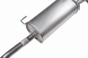
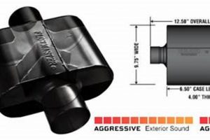
A visual representation displaying the components of an automotive exhaust silencing device, often illustrating their spatial relationships and connections, is a schematic of considerable practical use. These depictions typically feature labeled depictions of core elements, such as the inlet pipe, baffles, resonators, and the outer casing, enabling clear understanding of their assembly and function. As an instance, an exploded-view illustration can clarify the arrangement of internal chambers within a specific model.
These schematics provide significant advantages for maintenance, repair, and modification purposes. They aid in identifying individual components required for replacement, facilitating accurate ordering of replacement hardware. Moreover, the diagrams offer insight into the internal mechanics responsible for sound attenuation. Historically, these illustrations were found primarily in paper-based repair manuals; however, digital formats have significantly improved accessibility and interactivity.
The following sections will delve into the specific components usually found within this kind of visual depiction, discuss common failures that can be identified using them, and explore how these schematics assist in performing effective repairs and modifications.
Insights on Utilizing Schematics of Exhaust Silencing Devices
The following recommendations are designed to enhance the effective utilization of these schematics for repair, maintenance, and diagnostic procedures.
Tip 1: Prioritize Accuracy of the Schematic: Verification of the depiction’s relevance to the specific vehicle make, model, and year is paramount. A discrepancy in the reference material can lead to inaccurate component identification and subsequent errors in parts procurement.
Tip 2: Leverage Exploded Views for Assembly Understanding: Exploded views, detailing component separation, are valuable for comprehending assembly order. Careful study of these views will minimize the risk of incorrect reassembly following maintenance.
Tip 3: Pay Attention to Part Numbers and Nomenclature: Most schematics include standardized part numbers and nomenclature. Use these identifiers to ensure precise ordering of replacement components from suppliers. Cross-reference these numbers with vendor catalogs where feasible.
Tip 4: Examine Welding Points and Seam Locations: The schematic will often highlight critical welding points or seam locations. During repair, pay close attention to these areas, ensuring structural integrity is maintained if any welding work is performed.
Tip 5: Utilize Digital Resources for Enhanced Detail: When available, digital schematics offer superior resolution and zoom capabilities. Exploit these features to scrutinize fine details regarding component geometry and fitment.
Tip 6: Document the Disassembly Process: Even with a detailed schematic, it is advisable to document the disassembly process with photographs or notes. This provides a valuable reference point during reassembly, especially when dealing with complex configurations.
Tip 7: Consult Multiple Sources for Confirmation: Whenever possible, cross-reference the schematic with other repair resources, such as service manuals or online forums. This ensures validation of the information and reduces the risk of misinterpretation.
Adherence to these recommendations should facilitate more efficient and accurate utilization of schematics, ultimately streamlining repairs and maintenance activities.
The final section will consolidate the core concepts discussed throughout the article.
1. Component Identification
Accurate component identification is inextricably linked to the effective utilization of a muffler parts diagram. The primary function of such a diagram is to provide a visual key for distinguishing and locating individual elements within the exhaust silencing device. This relationship is causal: the diagram is created to enable component identification, and the diagram’s effectiveness is directly proportional to the ease and accuracy with which one can identify the parts using it. For example, if a technician needs to replace a specific baffle within a muffler, the diagram allows them to pinpoint the exact component, avoiding unnecessary disassembly or the ordering of incorrect parts.
Component identification, as facilitated by the visual schematic, is not merely an academic exercise; it has substantial practical implications. In automotive repair settings, misidentification of parts can lead to wasted time, increased labor costs, and potential damage to other components. A clear diagram assists in determining whether a particular sound attenuation issue stems from a failed resonator, a corroded inlet pipe, or a damaged baffle plate. Furthermore, correct component identification is crucial when modifying an exhaust system for performance enhancements, ensuring that any aftermarket parts are compatible with the original configuration. Consider, for example, attempting to replace a catalytic converter without properly identifying its connection points; such a scenario can result in installation errors and environmental non-compliance.
In conclusion, component identification represents a cornerstone of effective muffler maintenance and modification, with the parts diagram serving as an indispensable tool for achieving accurate identification. While challenges may arise due to variations in muffler designs across different vehicle models, the consistent application of these diagrams significantly reduces the risk of error. The connection underscores the broader theme of precision and informed decision-making in automotive repair and maintenance, highlighting the necessity of visual aids in navigating the complexities of mechanical systems.
2. Assembly Arrangement
The assembly arrangement, as visually represented in a muffler parts diagram, dictates the operational effectiveness and acoustic properties of the exhaust silencing device. The diagram meticulously outlines the spatial relationship between various components, including the inlet pipe, resonators, baffles, and outlet pipe. This representation is not arbitrary; rather, it directly reflects the intended flow path of exhaust gases and the sequence of sound wave interference and dissipation intended to reduce noise emissions. Alterations to the depicted assembly arrangement, without a thorough understanding of the underlying acoustic principles, can drastically alter the muffler’s performance, potentially increasing noise levels or reducing engine efficiency. A cause-and-effect relationship is inherent: the diagram dictates the correct assembly, and deviations from it can directly result in undesirable outcomes.
The importance of assembly arrangement is further underscored by the complexities of modern exhaust systems, which often incorporate multiple chambers and strategically placed baffles to achieve specific acoustic profiles. The parts diagram serves as a crucial reference point during repairs or modifications, ensuring that these intricate internal configurations are maintained. For example, during the replacement of a corroded resonator, the diagram clearly illustrates its orientation and position relative to other components, preventing incorrect installation that could compromise the muffler’s sound attenuation capabilities. Furthermore, the diagram facilitates the identification of potential assembly errors introduced during manufacturing or previous repair attempts. The practical significance is evident in the reduction of diagnostic time and the prevention of costly rework resulting from improper assembly.
In summary, the assembly arrangement component of a muffler parts diagram provides essential information for ensuring correct muffler function. This knowledge enables precise repairs and modifications, preserving acoustic performance and minimizing the risk of assembly-related malfunctions. The diagram serves as a tangible guide for maintaining the intended functionality of the exhaust system, demonstrating the direct correlation between the depicted assembly and the resulting operational characteristics.
3. Part Numbering System
The part numbering system, as integrated within a muffler parts diagram, constitutes a critical element for accurate component identification and procurement. Each element depicted on the schematic is typically assigned a unique identifier, adhering to a standardized system dictated either by the vehicle manufacturer or the aftermarket parts supplier. The function of this system is to directly correlate the visual representation of a component with its corresponding ordering information. Incorrect interpretation or disregard for this numbering system can result in the acquisition of incompatible parts, leading to delays, increased costs, and potential damage to the exhaust system. A cause-and-effect relationship exists: the part number allows identification, and failing to use the correct number leads to procurement errors.
The importance of the part numbering system is accentuated by the complexity of modern muffler designs and the subtle variations that can exist between seemingly identical components across different vehicle models or production years. For instance, two mufflers may appear externally similar, yet feature differing internal baffle configurations or connection point geometries. The part number, in these cases, serves as the definitive differentiating factor, ensuring that the correct replacement is selected. In practical terms, a technician attempting to replace a damaged resonator relies on the part number shown on the diagram to order the precise component that will fit and function correctly within the existing exhaust system. Neglecting this critical step can lead to significant installation difficulties or performance degradation.
In summary, the part numbering system significantly enhances the utility of the muffler parts diagram, providing a bridge between visual identification and accurate parts procurement. The implementation of this system minimizes the risk of errors during repairs and modifications, ensuring proper fit and function of replacement components. While challenges may arise due to inconsistencies in numbering conventions across different manufacturers, the consistent and careful application of these identifiers remains essential for efficient and effective muffler maintenance.
4. Material Specifications
The material specifications detailed in a muffler parts diagram represent a crucial element for ensuring the longevity, performance, and safety of the exhaust silencing device. These specifications provide vital information regarding the composition and properties of each component, enabling informed decisions during repair, replacement, or modification.
- Corrosion Resistance
Material selection directly affects the muffler’s ability to withstand corrosive environments, primarily from exposure to exhaust gases, road salts, and moisture. Diagrams often specify materials like stainless steel or aluminized steel for components susceptible to corrosion, ensuring extended service life. Failure to adhere to these specifications can lead to premature degradation and failure of the muffler.
- Temperature Tolerance
Exhaust systems operate at elevated temperatures, necessitating materials that can maintain their structural integrity and mechanical properties under such conditions. Diagrams specify materials with high melting points and resistance to thermal fatigue, preventing warping, cracking, or other forms of heat-related damage. Substitution with materials lacking adequate temperature tolerance can lead to dangerous exhaust leaks or catastrophic muffler failure.
- Material Thickness and Gauge
The diagram provides data on the material thickness of various muffler components. Material gauge influences durability, noise reduction, and overall weight. Selecting components with correct thickness as specified prevents premature wear-through and structural failure due to vibration or impact, ensuring the exhaust system meets established performance parameters. Deviations from specified thickness and gauge can impact sound damping efficiency.
- Welding Compatibility
Many mufflers are constructed using welding techniques. The diagram may denote materials compatible with specific welding processes, such as MIG or TIG welding, to maintain the structural integrity of welded joints. Using incompatible materials in welding can result in weak or porous welds, leading to premature failure and exhaust leaks. Proper selection and compatibility is essential to maintain system integrity under stress.
The inclusion of material specifications within the muffler parts diagram ensures that repairs and modifications are conducted using appropriate materials, safeguarding the functionality and safety of the exhaust system. The adherence to these specifications is paramount for preventing premature failure, maintaining acoustic performance, and complying with environmental regulations.
5. Internal Structure
The internal structure, as depicted in a muffler parts diagram, is fundamental to understanding the device’s function and performance. The diagram provides a visual representation of the arrangement of chambers, baffles, and resonators within the muffler, crucial for effective sound attenuation.
- Baffle Configuration and Sound Wave Interference
The arrangement of baffles directly influences sound wave propagation and interference within the muffler. Diagrams illustrate the position and orientation of baffles, dictating how sound waves are reflected, absorbed, and canceled out. Variations in baffle design impact the muffler’s overall noise reduction capabilities. For example, a diagram might show staggered baffles to maximize path length and increase destructive interference. Improper baffle configuration, resulting from incorrect repairs based on misinterpreted diagrams, can lead to increased noise levels.
- Resonator Placement and Frequency Tuning
Resonators are specifically tuned chambers designed to attenuate specific frequencies of sound. The muffler parts diagram reveals the size, shape, and location of resonators within the muffler’s internal structure. These details are crucial for understanding how the muffler targets and reduces unwanted frequencies. A Helmholtz resonator, for instance, may be strategically positioned to dampen a particular engine resonance. Incorrect resonator placement, due to errors in assembly guided by an inaccurate diagram, can compromise the muffler’s effectiveness in reducing noise.
- Chamber Volume and Gas Flow Dynamics
The volume and shape of internal chambers influence the flow of exhaust gases and the dissipation of acoustic energy. Muffler parts diagrams provide dimensional information about these chambers, allowing for analysis of gas flow dynamics. Large chambers might promote expansion and cooling of gases, while narrow passages can increase turbulence and sound absorption. Alterations to chamber volume, resulting from unauthorized modifications not aligned with the diagram, can negatively impact engine performance or increase backpressure.
- Material Composition and Acoustic Properties
While not always explicitly stated, the diagram, in conjunction with supplementary materials, hints at the types of materials employed in the internal structure (e.g., steel gauge, perforation patterns). These materials possess distinct acoustic properties that contribute to sound attenuation. Perforated tubes, for example, allow sound waves to enter the surrounding absorption material. Failure to consider material properties during repairs, substituting inappropriate materials based on an incomplete understanding of the diagram, can compromise the muffler’s acoustic performance and durability.
The internal structure is central to the muffler’s functionality, with its visual depiction in the muffler parts diagram providing invaluable insights into its operation and serving as a guide for proper maintenance and repair. The arrangement of the internal structure significantly influences how efficiently and effectively a muffler attenuates engine exhaust sound.
Frequently Asked Questions
The following addresses common inquiries regarding the utilization and interpretation of visual schematics depicting exhaust silencing devices.
Question 1: What is the primary purpose of a muffler parts diagram?
The primary purpose is to provide a visual guide to the components of an exhaust silencing device, aiding in identification, repair, and modification processes. The diagram clarifies the arrangement and interconnection of individual parts.
Question 2: Where can a reliable muffler parts diagram be located?
Reliable schematics are often found in vehicle-specific service manuals, online parts catalogs, and databases provided by automotive manufacturers or reputable aftermarket suppliers. Verification of the diagram’s accuracy against the vehicle’s make, model, and year is crucial.
Question 3: Why is it important to adhere to the part numbering system indicated on the diagram?
Adherence ensures accurate component procurement. The part number serves as a unique identifier, distinguishing between seemingly identical parts and preventing the acquisition of incompatible components.
Question 4: Can a muffler parts diagram assist in diagnosing exhaust system problems?
Yes, by visually identifying the location of potential failures, such as corroded baffles or damaged resonators, the diagram aids in pinpointing the source of exhaust system issues. It allows for targeted inspection of specific components.
Question 5: Does the diagram provide information about the materials used in different muffler components?
Some schematics may include material specifications, indicating the types of steel or other alloys used in the construction of individual parts. This information is crucial for ensuring compatibility during repairs or modifications and maintaining the muffler’s corrosion resistance and temperature tolerance.
Question 6: Is the assembly arrangement illustrated in the diagram important for proper muffler function?
The assembly arrangement is essential. The diagram dictates the correct spatial relationship between components, ensuring proper sound attenuation and exhaust gas flow. Deviations from the illustrated arrangement can compromise the muffler’s performance and potentially increase noise levels.
Accurate interpretation and adherence to the information provided in the parts diagram are critical for effective exhaust system maintenance and repair. It facilitates informed decision-making and minimizes the risk of errors.
The subsequent article section provides a summary of the core concepts discussed.
Conclusion
This exploration has emphasized the crucial role of a muffler parts diagram in automotive maintenance and repair. It serves as a visual reference for component identification, assembly arrangement, part numbering, material specifications, and internal structure. Accurate interpretation and diligent application of the information contained within these diagrams are paramount for ensuring effective exhaust system maintenance and modifications.
Continued reliance on comprehensive and accurate schematic representations of automotive components will remain critical for technicians and enthusiasts alike. By leveraging these resources, the longevity, performance, and safety of vehicle exhaust systems can be effectively maintained. This commitment to precision ultimately contributes to reduced environmental impact and enhanced operational efficiency.


